| Indoor Residential Load Center | Houses, apartments, small offices and light commercial interiors. | 120/240 V single-phase in many North American systems; 230/400 V single-phase or three-phase configurations are common in IEC-based markets. | Approximately 40–225 A, depending on the service rating and local design. | DIN-rail or plug-in miniature circuit breakers; optional residual-current and surge-protection devices. | Flush-mounted or surface-mounted inside a dry, accessible location. | Usually IP20 or similar indoor protection; the exact rating depends on the enclosure design. | Compact, economical and easy to expand for lighting, socket and appliance circuits. | Not suitable for rain, condensation, dust-heavy areas or direct outdoor exposure unless specifically rated. | Confirm local breaker dimensions, busbar configuration, neutral arrangement, service rating, short-circuit rating and applicable national code. |
| Outdoor Weatherproof Distribution Box | External walls, gardens, utility areas, small construction sites and outdoor equipment. | Commonly 230/400 V or 120/240 V, subject to the local supply system. | Approximately 40–250 A for small and medium distribution applications. | MCBs, RCDs/RCBOs, isolators and sometimes surge protective devices. | Surface-mounted, usually with cable glands and protected entry points. | Typically IP54–IP66 when correctly assembled and sealed; IP rating must be verified for the complete installation. | Improved protection against rain, dust and accidental contact; suitable for exposed service locations. | Higher cost and larger enclosure size; condensation control and UV resistance may be required. | Check IP rating, UV stability, impact resistance, gland compatibility, drainage, operating temperature and corrosion resistance. |
| Modular DIN-Rail Consumer Unit | Residential and light-commercial projects using modular protection and control devices. | Typically 230/400 V AC in IEC-oriented systems. | Usually 40–160 A main incoming rating, with branch circuits selected according to the load. | DIN-rail MCBs, RCBOs, RCDs, contactors, meters and surge protection modules. | Flush or surface mounting; modular rows support future additions. | Commonly IP30–IP40 for indoor use, depending on the door, cover and installation conditions. | Flexible layout, straightforward replacement and good compatibility with modular accessories. | Requires accurate rail spacing, phase distribution and busbar selection; exposed locations need a higher-rated enclosure. | Verify module width, number of ways, busbar pitch, neutral and earth terminals, spare capacity and local wiring rules. |
| Main Breaker Panelboard | Commercial buildings, workshops, retail premises and larger residential services. | Commonly 230/400 V or 120/208 V and 277/480 V three-phase systems, depending on the region. | Approximately 100–1,200 A, with higher ratings available through engineered assemblies. | Main circuit breaker with bolt-on, plug-in or withdrawable branch breakers. | Usually floor-standing or wall-mounted, depending on rating and available space. | Indoor versions are often IP30–IP42; outdoor versions require a suitable weatherproof enclosure. | Supports higher loads, coordinated feeder distribution and structured branch-circuit management. | Needs more installation space, stronger cable termination and professional fault-current assessment. | Confirm incoming rating, busbar rating, interrupting capacity, number of outgoing ways, cable space and maintenance access. |
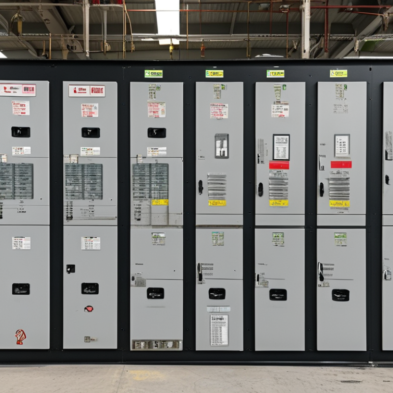
| Low-Voltage Switchboard | Factories, data centers, hospitals, infrastructure facilities and large commercial buildings. | Commonly up to 1,000 V AC in low-voltage distribution systems; project voltage must be confirmed. | Typically 400–6,300 A for main busbars, depending on the engineered assembly. | Air circuit breakers, molded-case circuit breakers, metering, protection relays and bus-coupler sections. | Floor-standing, compartmentalized and assembled in sections. | Indoor or outdoor ratings vary; IP31–IP54 ranges are common for many assemblies, but the certified design controls. | High capacity, improved segregation, serviceability and options for selective coordination. | Higher procurement cost, engineering requirements, transport complexity and longer project lead time. | Review assembly verification, short-time withstand current, temperature rise, internal separation, arc-fault requirements and local certification. |
| Molded-Case Circuit Breaker Enclosure | Motor feeders, pumps, HVAC systems, industrial machinery and high-current branch circuits. | Commonly 230–690 V AC, depending on the breaker and system design. | Approximately 100–1,600 A for many standard applications; engineered ranges can be higher. | Molded-case circuit breakers with thermal-magnetic or electronic trip units. | Wall-mounted or installed inside a panel or switchboard. | Indoor and outdoor enclosures are available; protection commonly ranges from IP30 to IP66 by design. | High interrupting capability, adjustable protection options and suitability for demanding feeders. | Bulkier and more expensive than miniature breakers; thermal management may be necessary at high loads. | Check rated current, interrupting capacity, trip curve, adjustable settings, terminal size, enclosure heat dissipation and coordination. |
| Motor Control and Protection Box | Industrial motors, pumps, compressors, fans, conveyors and packaged machinery. | Commonly 230/400 V or 400/690 V AC three-phase systems. | Typically sized for motor full-load current, often from less than 1 A to several hundred amperes. | Short-circuit protective device, motor overload relay, contactor, isolator and optional soft starter or variable-speed drive. | Wall-mounted or integrated into a motor control center or machine enclosure. | Often IP54–IP66 for industrial environments, subject to enclosure and gland configuration. | Combines isolation, overload protection and motor switching in one coordinated assembly. | Motor starting current, heat generation, electromagnetic compatibility and maintenance access require careful design. | Confirm motor data, starting method, service factor, overload class, fault level, enclosure ventilation and emergency-stop requirements. |
| Solar PV Combiner and DC Protection Box | Rooftop and ground-mounted photovoltaic systems between PV strings and the inverter. | DC voltage varies by system; common designs may be 600 V, 1,000 V or 1,500 V DC, subject to component ratings. | String and array currents are determined by module configuration; many designs use PV string fuses or DC breakers in the tens of amperes. | DC-rated fuses or circuit breakers, DC isolator, surge protective device and string monitoring where required. | Outdoor wall-mounted or equipment-mounted enclosure. | Commonly IP65 or higher for outdoor PV installations, with UV-resistant materials and sealed cable entries. | Centralizes string protection, simplifies maintenance and helps manage DC surge exposure. | AC breakers cannot automatically be substituted for DC devices; polarity, arc interruption and thermal derating are critical. | Verify maximum system voltage, short-circuit current, polarity, DC interrupting rating, PV fuse class, SPD type and environmental rating. |
| EV Charging Distribution Box | Residential, workplace, fleet and public electric-vehicle charging installations. | Commonly 230 V single-phase or 400 V three-phase AC; charger-specific requirements apply. | Often 16–63 A per charging circuit, with the upstream distribution rating based on diversity and total demand. | MCB or MCCB, residual-current protection, surge protection and energy metering where required. | Indoor or outdoor wall-mounted installation near the charging equipment. | Typically IP54–IP66 for exposed locations; the rating must match the charger environment. | Provides dedicated protection and supports load management for multiple chargers. | Residual-current protection requirements differ by charger design and jurisdiction; continuous-load heating must be considered. | Check charger current, phase arrangement, RCD type, DC residual-current detection, cable size, load balancing and utility connection limits. |
| Temporary Construction Distribution Box | Construction sites, temporary events, maintenance areas and mobile work facilities. | Commonly 230/400 V AC three-phase or 120/240 V AC, depending on the temporary supply. | Approximately 16–250 A for portable and site distribution units. | Incoming isolator, MCBs, RCDs/RCBOs, socket outlets and sometimes meters. | Portable, wall-mounted, pole-mounted or installed on a temporary support frame. | Typically IP44–IP67, depending on exposure, socket configuration and mobility requirements. | Rugged, easy to relocate and designed for frequent connection and disconnection. | Subject to mechanical damage, cable movement, moisture and changing site conditions. | Confirm impact resistance, RCD test function, socket standards, cable protection, earthing arrangement and inspection requirements. |
| Marine and Coastal Distribution Box | Boats, ports, waterfront buildings, offshore support areas and salt-laden coastal environments. | Project-specific AC or DC systems, commonly including 230/400 V AC or low-voltage DC control systems. | From small branch circuits to engineered low-voltage distribution ratings. | Corrosion-resistant breakers, isolators, RCDs and marine-rated protection accessories. | Surface-mounted with secure fastening and sealed cable entries. | Usually IP56–IP66 or higher, with corrosion-resistant enclosure materials and hardware. | Improved resistance to salt spray, vibration, humidity and harsh operating conditions. | Material compatibility, galvanic corrosion and condensation control can significantly affect service life. | Check marine or offshore approvals where required, salt-spray performance, vibration resistance, gland materials and bonding requirements. |
| Hazardous-Area Certified Enclosure | Petrochemical facilities, chemical plants, fuel storage, grain processing and areas with flammable gas or dust. | Voltage and current depend on the certified equipment and area classification. | Project-specific; commonly used for selected branch, control and local isolation circuits. | Certified breakers, isolators, fuses or motor protection devices inside an approved enclosure. | Surface-mounted or equipment-mounted according to the hazardous-area design. | Certification-specific protection, often including a robust IP rating such as IP54–IP66. | Designed to limit ignition risk when correctly selected and installed. | Higher cost, limited component compatibility and strict installation, inspection and maintenance controls. | Match the exact zone or division, gas or dust group, temperature class, equipment protection level, certificate and cable-entry method. |