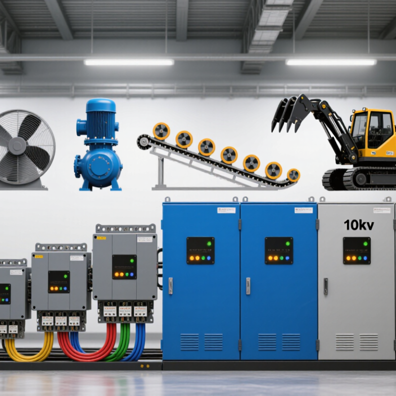
| Voltage and Motor Compatibility |
| Low-voltage supply | 380–415 V AC, 50 Hz; commonly used with 380 V, 400 V, or 415 V three-phase motors | Controls the applied RMS voltage during acceleration through semiconductor switches, reducing the motor's initial inrush current. | Confirm the actual line-to-line voltage, frequency, phase sequence, motor nameplate current, and available short-circuit current. |
| Medium-voltage supply | 3.3 kV, 4.16 kV, 6 kV, 6.6 kV, and 10 kV classes | Uses medium-voltage thyristor stacks and insulation systems to ramp motor voltage while limiting transformer and feeder voltage disturbance. | Select a unit with a voltage rating equal to or higher than the system's maximum operating voltage and suitable insulation coordination. |
| Motor connection | Three-phase induction motor; squirrel-cage motors are the most common application | The starter regulates the stator voltage; it does not normally change the motor's operating speed after bypass. | Verify whether the motor has six accessible terminals when an inside-delta connection is proposed. |
| Frequency | 50 Hz or 60 Hz | Changes motor reactance, acceleration behavior, and the relationship between voltage, current, and torque. | Use a starter rated for the actual operating frequency; do not assume a 50 Hz setting is interchangeable with 60 Hz. |
| Starting Current and Torque Control |
| Across-the-line starting current | Typically about 5–8 times motor full-load current for a standard squirrel-cage induction motor | Creates high voltage drop, mechanical shock, and thermal stress during direct-on-line starting. | Use the motor manufacturer's locked-rotor current when calculating the actual worst-case starting condition. |
| Soft-starter current limit | Common adjustable range: approximately 2–5 times motor full-load current, depending on load and starter rating | Limits the maximum current by controlling thyristor firing angle and therefore the voltage applied to the motor. | Set the lowest limit that still produces reliable acceleration. Excessively low current can cause a stalled or overheated motor. |
| Voltage ramp time | Common adjustment range: approximately 1–60 seconds | Longer ramps generally reduce acceleration shock, but they do not guarantee lower peak current if the load requires high torque. | Begin with the motor and load manufacturer's recommended value, then verify acceleration time and motor temperature. |
| Initial voltage | Common adjustment range: approximately 20–80% of rated motor voltage | Motor starting torque is approximately proportional to the square of applied voltage under simplified induction-motor conditions. For example, 70% voltage produces roughly 49% of the theoretical locked-rotor torque. | Increase initial voltage only enough to overcome static friction and begin smooth rotation. |
| Starting torque | Often adjustable to approximately 10–80% of motor locked-rotor torque, depending on motor and control method | Too little torque causes a long acceleration time or stall; too much torque increases mechanical stress and current. | Compare the motor torque curve with the pump, fan, compressor, conveyor, or crusher load curve. |
| Current-limited acceleration | Typically selected when the electrical network has limited capacity or the motor drives a high-inertia load | Maintains current near a configured ceiling while the motor accelerates, rather than following only a fixed voltage ramp. | Prefer current-limit control when voltage-drop limits are more important than a fixed acceleration time. |
| Torque-control ramp | Available on advanced units; ramp time commonly configured from a few seconds to tens of seconds | Regulates estimated motor torque to provide smoother acceleration and deceleration than voltage ramp control. | Useful for pumps, conveyors, and systems where hydraulic surge or belt shock must be minimized. |
| Application and Load Requirements |
| Centrifugal pump | Typical starting torque demand: low to moderate; load torque rises approximately with speed squared | A smooth voltage or torque ramp can reduce water hammer and pipe pressure transients. | Specify pump stop control, soft stop, and underload or dry-run protection where required. |
| Fan or blower | Typical starting torque demand: low to moderate; fan load torque generally rises approximately with speed squared | Limits current while allowing a gradual increase in torque and airflow. | Check the fan's inertia and acceleration time; a long ramp may require a higher thermal duty rating. |
| Conveyor | Typical starting torque demand: moderate to high, especially with a loaded belt or inclined conveyor | Controlled torque reduces belt jerk, product movement, and coupling stress. | Check breakaway torque, loaded-start frequency, belt tension, and whether reverse or anti-jam functions are needed. |
| Compressor | Starting torque varies widely; reciprocating types may have high breakaway torque | Current limiting may extend acceleration if compression pressure is not unloaded. | Confirm the compressor unloading system, restart interval, and allowable starts per hour. |
| Crusher, mill, or high-inertia machine | High inertia and potentially high breakaway torque | Requires sufficient starting torque and thermal capacity; an aggressive current limit may prevent acceleration. | Consider a larger starter frame, a longer-duty rating, or an alternative starting method after a complete load study. |
| Electrical and Thermal Ratings |
| Starter continuous current rating | Must be at least equal to the motor full-load current at the selected voltage and duty | Determines the semiconductor, heat-sink, and bypass-contactor thermal capability. | Size from motor nameplate current, not motor horsepower alone. Apply derating for altitude, enclosure temperature, and frequent starts. |
| Typical overload capability | Common electronic protection settings include approximately 105–120% of motor full-load current for thermal overload thresholds; actual values vary | Protects the motor from prolonged overload while allowing normal acceleration. | Set overload protection to the motor manufacturer's service factor and thermal limits, coordinated with upstream protection. |
| Starting duty | Light, standard, or heavy duty; commonly specified by starts per hour and starting duration | Repeated or extended starts increase thyristor and motor heating even when the running current is normal. | Provide the number of starts per hour, average start duration, rest interval, and load inertia to the supplier or design engineer. |
| Bypass contactor | Normally closes after acceleration; may be internal or externally installed | Removes most semiconductor conduction losses during normal running and reduces heat generation. | Check bypass contactor AC-3 or equivalent motor duty rating, interlocking, and short-circuit coordination. |
| Power factor during starting | Low and load-dependent during induction-motor starting | Current reduction does not necessarily mean proportional reduction in starting kVA or acceleration time. | Evaluate the complete motor-load-network behavior rather than selecting solely by nominal current reduction. |
| Harmonic impact | Primarily associated with phase-angle control during ramping; usually much lower after bypass | May produce waveform distortion and additional heating during acceleration. | Check local harmonic limits, generator compatibility, transformer impedance, and the number of starts per hour. |
| Protection, Installation, and Control Features |
| Common motor protections | Overload, phase loss, phase imbalance, overtemperature, excessive starts, stall, and undercurrent | Prevents damage caused by abnormal supply conditions, stalled acceleration, or inadequate cooling. | Confirm which protections are built in and which require external sensors, relays, or a motor protection system. |
| Thermal sensor input | Often supports PTC, RTD, or a dedicated motor thermal switch, depending on the design | Provides direct temperature supervision when current-based thermal estimation is insufficient. | Match the input type, sensor wiring, insulation rating, and trip logic to the motor documentation. |
| Control voltage | Common control supplies include 24 V AC/DC, 110–120 V AC, and 220–240 V AC | Does not determine motor starting torque directly, but incorrect control voltage can cause unreliable operation. | Specify the available control supply separately from the motor power voltage. |
| Communication | Optional industrial communication may include Modbus RTU, Modbus TCP, EtherNet/IP, or other protocols | Enables remote monitoring of current, thermal state, faults, start count, and operating status. | Confirm protocol, network topology, cybersecurity requirements, and whether an option module is required. |
| Enclosure and environmental rating | Common low-voltage enclosure ratings include IP20 for switchboard installation and IP54 or higher for protected field cabinets | Environmental conditions affect cooling, insulation life, and reliable thyristor operation. | Check ambient temperature, humidity, dust, corrosive gases, altitude, ventilation, and the required IP or NEMA rating. |
| Medium-voltage isolation | Requires rated isolation, grounding, interlocking, discharge provisions, and safe access procedures | Does not change the control principle, but greatly affects system safety and maintainability at 3.3–10 kV. | Use qualified medium-voltage engineering and verify compliance with applicable local electrical safety rules. |
| Selection Checklist by Voltage Class |
| 380–415 V motor starter | Suitable for low-voltage three-phase motors; current selected from the motor nameplate FLC | Usually offers the broadest range of control, bypass, and protection functions. | Check line current, motor connection, enclosure heat dissipation, bypass arrangement, and short-circuit rating. |
| 3.3–4.16 kV motor starter | Medium-voltage construction with phase-isolated power assemblies | Reduces feeder voltage dip and mechanical stress while maintaining medium-voltage motor operation. | Confirm insulation coordination, cable termination, grounding, vacuum contactor arrangement, and service access. |
| 6–6.6 kV motor starter | Common medium-voltage class for industrial pumps, fans, compressors, and process machinery | Provides controlled acceleration for large motors that would impose substantial inrush on the utility or plant network. | Perform a short-circuit, voltage-drop, motor acceleration, and protection-coordination study before purchase. |
| 10 kV motor starter | High medium-voltage application requiring an appropriately rated switchgear and insulation system | Controls the high-power motor starting event without applying full locked-rotor current immediately. | Specify maximum system voltage, power-frequency withstand, impulse withstand, grounding method, and site safety requirements. |
| Soft Starter Versus Other Starting Methods |
| Soft starter | Reduced-voltage starting; full-speed operation after bypass | Reduces starting current and torque shock but does not provide continuous speed control. | Best for fixed-speed applications that need smoother starting and stopping with relatively low running losses. |
| Variable-frequency drive | Controls both frequency and voltage across the operating range | Can provide high starting torque at controlled current and continuous speed regulation, but adds more installation and harmonic considerations. | Choose when process speed control, energy optimization, or frequent speed changes are required. |
| Star-delta starter | Reduced-voltage electromechanical starting; typically approximately one-third of direct-on-line starting torque in the star connection | Provides a fixed reduction rather than a continuously adjustable ramp and requires a compatible six-terminal motor. | Consider only where the load can accelerate with the reduced starting torque and the transition is acceptable. |
| Autotransformer starter | Reduced-voltage starting using transformer taps | Can provide higher motor terminal voltage and starting torque than some fixed reduced-voltage methods, but equipment is larger and more complex. | Evaluate where high starting torque and reduced line current are both required without variable-speed operation. |
| Buyer Decision Criteria |
| Recommended minimum information for sizing | Motor voltage, rated power, full-load current, frequency, service factor, locked-rotor current, load type, inertia, starts per hour, acceleration time, and ambient conditions | These values determine whether the starter can deliver enough torque without exceeding current or thermal limits. | Do not select by motor power alone, especially for high-inertia, high-breakaway-torque, or frequently started loads. |
| Voltage-drop target | Project-specific; often constrained by sensitive loads, generator capacity, transformer impedance, and utility requirements | Lower starting current generally reduces the temporary feeder voltage drop, but the result depends on system impedance. | Calculate voltage drop using the complete source, transformer, cable, and motor network. |
| Acceleration verification | Motor torque must remain above load torque throughout the acceleration period | Current limiting that is too restrictive can extend acceleration excessively or cause a stall. | Validate the acceleration curve during commissioning and record current, voltage, time, and motor temperature. |
| Safety and compliance | Applicable requirements may include IEC 60947-4-2 for AC semiconductor motor controllers and starters, plus local installation rules | Standards address equipment performance, testing, insulation, and coordination requirements. | Verify the exact edition and application of all standards required at the installation site. |
| Overall recommendation | Match voltage, current, load torque, duty, environment, and protection requirements | A properly sized soft starter can reduce inrush and mechanical shock while preserving efficient full-speed operation after bypass. | Always confirm final settings and coordination through the motor, load, and electrical-system studies. |