


- Home
- A-Z Catalogue
- Products
- Valves
- Cetop
- Manual Directional Valves
- Proportional Valves
- Poppet Valves
- High-Speed Linear Servo Valves
- All High-Speed Linear Servo Valves
- Cetop 10 (NG32) Two Stage Type High Speed Linear Servo Valves – LSVHG-10
- Cetop 10 (NG32) Two Stage Type High Speed Linear Servo Valves – LSVHG-10 (With Fail-Safe)
- Cetop 8 (NG25) Two Stage Type High Speed Linear Servo Valves – LSVHG-06
- Cetop 8 (NG25) Two Stage Type High Speed Linear Servo Valves – LSVHG-06 (With Fail-Safe)
- Cetop 7 (NG16) Two Stage Type High Speed Linear Servo Valves – LSVHG-04
- Cetop 7 (NG16) Two Stage Type High Speed Linear Servo Valves – LSVHG-04 (With Fail-Safe)
- Cetop 5 (NG10) Direct Type High Speed Linear Servo Valves – LSVG-03
- Cetop 5 (NG10) OBE Type Direct Operated Linear Servo Valves – LSVG-03-EH
- Cetop 3 (NG6) OBE Type Direct Operated Linear Servo Valves – LSVG-01-EH
- Pumps
- Pressure control
- Flow Control Valves
- Pressure Control Valves
- All Pressure Control Valves
- Brake Valves
- Direct Relief Valve
- Low Noise Solenoid Controlled Relief Valves
- Low Noise Pilot Operated Relief Valves
- Pilot Operated Relief Valves
- Pressure reducing and relieving valves
- Pressure reducing and check valves
- Pressure control valves
- Remote Control Relief Valves
- Solenoid Controlled Relief Valves – BSG
- Solenoid Controlled Relief Valves – BST
- Unloading relief valves
- Check valves
- Environmental
- Valves
- Hydraulic Systems
- Power pack
- About Us
- Contact
- Blog

7 Tips for Choosing Optical Cable Adapters
Optical Cable Adapters look small, yet they influence alignment, signal loss, and maintenance time across a fiber network. A poorly matched adapter can create reflection, loosen under vibration, or complicate future upgrades. These details matter more as networks become denser.
Cisco’s Annual Internet Report (2018–2023) projected 5.3 billion internet users and 29.3 billion networked devices by 2023. That scale places greater pressure on stable fiber connections. The ITU’s Facts and Figures 2023 reported that 67% of the world’s population used the internet. More connected endpoints mean more interfaces to inspect.
Small parts. Large consequences.
Choosing the right Optical Cable Adapters requires more than checking connector shape. Technicians should assess fiber mode, polish type, insertion loss, return loss, housing material, and environmental ratings. The adapter must also fit the panel, rack, or splice enclosure precisely. A blue SC/UPC adapter is not automatically suitable for a green SC/APC connection. Color can guide inspection, but specifications must decide.
This guide presents seven practical selection tips based on field experience, manufacturer specifications, and recognized industry data. It considers single-mode and multimode systems, common LC and SC formats, and demanding data-center conditions. No checklist is perfect. Real installations may expose overlooked dust, bend stress, or inconsistent labeling. That is why testing with calibrated equipment remains essential. Careful selection reduces rework, protects optical performance, and supports dependable network growth.
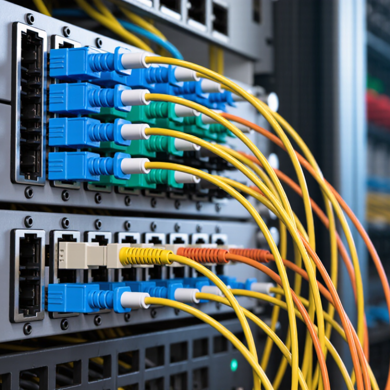
Table of Contents [Hide]
Understanding Optical Cable Adapter Types and Their Applications
Choosing an optical cable adapter starts with identifying the connector family and network environment. Common types include LC, SC, ST, and multi-fiber push-on adapters. LC adapters suit dense panels because their bodies are compact. SC adapters offer a larger push-pull housing, which helps technicians wearing gloves. ST adapters remain useful in older industrial and building systems.
Check the fiber mode before checking price. Single-mode adapters support long-distance links, while multimode adapters serve shorter data-center connections. Duplex adapters carry two fibers in one housing. Simplex versions carry one. For rack installations, choose keyed adapters, protective shutters, and accurate panel cutouts. A poor fit can increase insertion loss, even when the cable looks perfect. I have seen this overlooked.
Application details matter. Fiber-to-the-home networks often need sealed, durable adapter assemblies. Data centers usually prioritize density, polarity control, and quick maintenance. Industrial sites may require stronger retention and better dust protection. The ITU’s Facts and Figures 2023 reported 5.4 billion people online, showing why scalable connectivity infrastructure matters. The Cisco Annual Internet Report forecast 29.3 billion networked devices by 2023. Those figures do not measure adapters directly, but they explain rising pressure on fiber distribution systems. Before ordering, compare connector geometry, polish type, fiber mode, alignment sleeves, and operating temperature. Leave room for human error. Even experienced installers sometimes choose compatibility by appearance alone.





