


- Home
- A-Z Catalogue
- Products
- Valves
- Cetop
- Manual Directional Valves
- Proportional Valves
- Poppet Valves
- High-Speed Linear Servo Valves
- All High-Speed Linear Servo Valves
- Cetop 10 (NG32) Two Stage Type High Speed Linear Servo Valves – LSVHG-10
- Cetop 10 (NG32) Two Stage Type High Speed Linear Servo Valves – LSVHG-10 (With Fail-Safe)
- Cetop 8 (NG25) Two Stage Type High Speed Linear Servo Valves – LSVHG-06
- Cetop 8 (NG25) Two Stage Type High Speed Linear Servo Valves – LSVHG-06 (With Fail-Safe)
- Cetop 7 (NG16) Two Stage Type High Speed Linear Servo Valves – LSVHG-04
- Cetop 7 (NG16) Two Stage Type High Speed Linear Servo Valves – LSVHG-04 (With Fail-Safe)
- Cetop 5 (NG10) Direct Type High Speed Linear Servo Valves – LSVG-03
- Cetop 5 (NG10) OBE Type Direct Operated Linear Servo Valves – LSVG-03-EH
- Cetop 3 (NG6) OBE Type Direct Operated Linear Servo Valves – LSVG-01-EH
- Pumps
- Pressure control
- Flow Control Valves
- Pressure Control Valves
- All Pressure Control Valves
- Brake Valves
- Direct Relief Valve
- Low Noise Solenoid Controlled Relief Valves
- Low Noise Pilot Operated Relief Valves
- Pilot Operated Relief Valves
- Pressure reducing and relieving valves
- Pressure reducing and check valves
- Pressure control valves
- Remote Control Relief Valves
- Solenoid Controlled Relief Valves – BSG
- Solenoid Controlled Relief Valves – BST
- Unloading relief valves
- Check valves
- Environmental
- Valves
- Hydraulic Systems
- Power pack
- About Us
- Contact
- Blog

China Best Trailer Wiring Harness Supplier?
Finding the best trailer wiring harness supplier in China requires more than comparing prices on a product page. A reliable supplier should understand towing systems, vehicle compatibility, connector design, and long-term electrical performance. This guide examines how manufacturers produce a Trailer wiring harness, from copper conductors and insulation thickness to sealed terminals and protective sheathing.
Real-world details matter. A harness may face rain, road salt, engine heat, vibration, and repeated bending near the trailer connector. Strong suppliers should provide clear specifications, production samples, inspection records, and traceable quality controls. Useful questions include: Are the wires correctly gauged? Do the terminals resist corrosion? Are circuit labels easy to follow? Can the factory support custom lengths, plug types, and packaging?
The “best” supplier depends on your application. A company serving agricultural trailers may not suit an RV or commercial fleet project. Supplier experience, testing equipment, communication speed, and after-sales support all deserve careful review. Certifications can help, but documents alone do not prove consistent manufacturing quality. A factory audit, sample test, and small trial order often reveal more.
Be careful with attractive promises. Very low pricing may reflect thinner conductors or weaker connectors. I have also seen specifications that looked complete but lacked temperature or waterproofing details. That weakness deserves attention. A dependable Chinese supplier should explain limitations openly, correct design issues, and maintain consistent quality between batches. This article offers a practical framework for comparing candidates, reducing avoidable failures, and choosing a Trailer wiring harness partner with credible technical support.
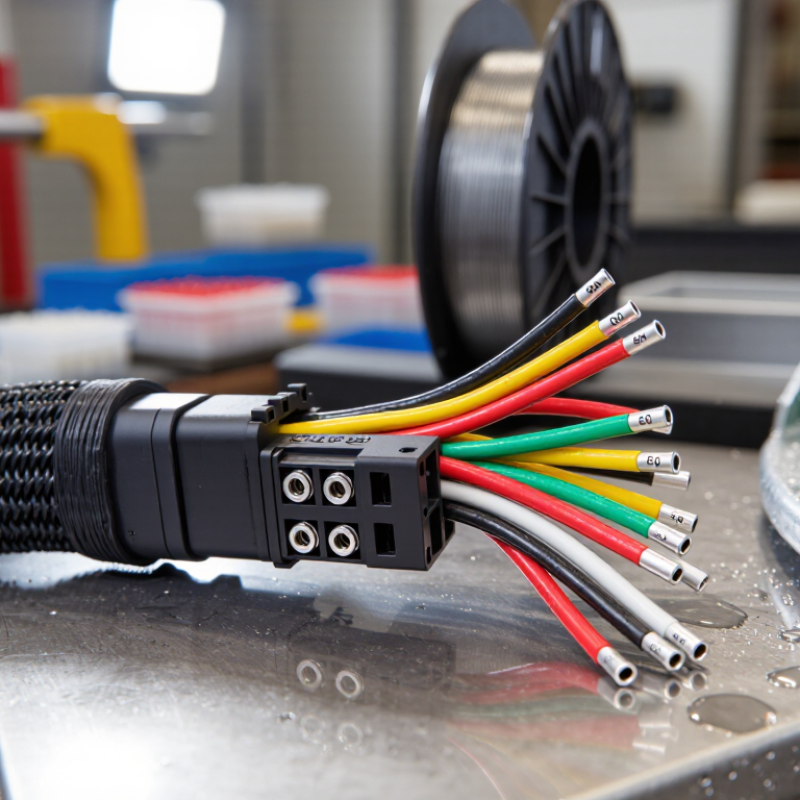
Table of Contents [Hide]
Trailer Wiring Harness Basics: 12V/24V Systems, Circuits, and Connector Types
Choosing a China-based trailer wiring harness supplier starts with electrical basics, not catalog size. A 12V system commonly uses seven-pin 12N layouts under ISO 1724. A 24V vehicle may follow ISO 1185’s 24N arrangement. Pin functions can differ between regions and vehicle classes. Voltage is not decoration. A 24V lamp connected to a 12V circuit may glow weakly. A 12V component exposed to 24V can fail quickly. Measure twice.
A harness supplier should provide current ratings, conductor sizes, insulation limits, and test records. Lighting circuits normally separate stop, tail, indicator, ground, and auxiliary feeds. The ground path deserves equal attention. Corrosion inside one socket can create dim lamps or intermittent braking signals. A 2024 global automotive wiring-harness market report forecasts growth above 6% annually through 2028. That figure suggests rising demand, not guaranteed quality. Ask for voltage-drop data under load, continuity checks, pull-force results, and water-ingress testing. These checks support the engineering principles used in SAE J560 and ISO connector standards.
Field testing often finds that neat molding hides poor crimp compression. A connector may pass continuity yet heat under load. That weakness is easy to miss. Request samples with labeled wires and sealed terminals. Check each pin against a test board. Cable length also matters. Excess slack can rub against the drawbar, while short wiring strains the plug. Ask for batch traceability, crimp-height records, and actual environmental test conditions. Measured evidence matters more than polished photographs.
China Best Trailer Wiring Harness Supplier? - Trailer Wiring Harness Basics: 12V/24V Systems, Circuits, and Connector Types
| System / Circuit | Typical Voltage | Primary Function | Common Circuit Arrangement | Typical Wire Size | Important Selection Notes |
|---|---|---|---|---|---|
| Basic 12 V lighting system | Nominal 12 V DC Approximately 12–14.7 V in operation | Road lighting and signaling | Ground, left turn/stop, right turn/stop, tail/marker | 16–18 AWG for many lighting circuits; 12–14 AWG for higher-current feeds | Use a dedicated ground path and protect exposed connections from moisture, abrasion, and corrosion. |
| 24 V lighting and auxiliary system | Nominal 24 V DC Approximately 24–29.4 V in operation | Lighting, control, and auxiliary power on selected vehicles | Same functional circuits as 12 V systems, with equipment rated for 24 V | Wire size depends on load and distance; current is lower for the same power than in a 12 V system | Do not connect 12 V-only lamps, modules, or accessories directly to a 24 V source. |
| Ground / return circuit | Matches the system voltage | Completes every electrical circuit | Dedicated ground wire from trailer connector to lamps and accessories, or an approved chassis-ground arrangement | Usually equal to or larger than the associated power wire | A weak ground can cause dim lights, flickering, cross-functioning, or intermittent operation. |
| Left turn / stop | 12 V or 24 V DC | Left-side turn signal and brake lamp | One combined circuit on many North American-style trailer systems | Typically 16–18 AWG, subject to load and cable length | Verify whether the towing vehicle combines or separates turn and stop signals. |
| Right turn / stop | 12 V or 24 V DC | Right-side turn signal and brake lamp | One combined circuit on many North American-style trailer systems | Typically 16–18 AWG, subject to load and cable length | Use a separate conductor from the left turn/stop circuit to maintain independent signaling. |
| Tail / running / marker lights | 12 V or 24 V DC | Rear lamps, side markers, clearance lamps, and license-plate lamp | Usually one shared lighting feed distributed along the trailer | Typically 16–18 AWG; larger conductors may reduce voltage drop on long trailers | Calculate total lamp load and inspect branch splices for sealed, strain-relieved connections. |
| Electric brake output | Usually 12 V DC; 24 V systems require compatible brake equipment | Carries the brake-controller signal to electric trailer brakes | Dedicated brake feed plus ground/return | Commonly 12–14 AWG, depending on brake count, current, and cable length | Use a correctly rated circuit protection device and size conductors for voltage drop and maximum brake current. |
| Auxiliary battery charge | 12 V or 24 V DC, depending on the vehicle and trailer system | Supplies charging current to a trailer battery or auxiliary equipment | Fused positive feed and dedicated return/ground | Often 10–12 AWG; final size depends on current, length, and allowable voltage drop | Use an appropriate fuse, relay, isolator, or charging controller where required by the vehicle design. |
| Reverse / auxiliary function | 12 V or 24 V DC | Reverse lamps, reverse lockout, work lamps, or another auxiliary function | Dedicated circuit assigned by the connector and vehicle wiring standard | Typically 14–18 AWG, based on the connected load | Confirm the pin assignment before connecting; unused pins should be sealed against water and debris. |
Common Trailer Connector Types
| Connector Type | Typical Number of Contacts | Typical Applications | Functions Commonly Supported | Selection Considerations |
|---|---|---|---|---|
| 4-way flat | 4 | Basic light-duty trailers | Ground, left turn/stop, right turn/stop, tail/running lights | Compact and economical, but it normally does not provide separate electric-brake, charging, or reverse circuits. |
| 5-way flat | 5 | Trailers requiring one additional auxiliary function | Basic lighting circuits plus a fifth circuit, often used for surge-brake reverse lockout | The fifth pin is not universally assigned; verify the towing vehicle and trailer pinout. |
| 6-way round | 6 | Utility, horse, and medium-duty trailers | Lighting, ground, electric brake output, and one auxiliary or charging circuit | Round housing offers a robust connection, but contact assignments can differ between installations. |
| 7-way RV-style blade | 7 | Travel trailers, caravans, and trailers with brakes | Lighting, ground, electric brakes, auxiliary battery charge, and reverse/auxiliary function | A common choice when multiple power and control circuits are needed; confirm the exact pinout and circuit protection. |
| 7-way round | 7 | Commercial, agricultural, and heavy-duty applications | Multiple lighting, braking, auxiliary, and power circuits | Select the connector based on mechanical locking, environmental sealing, contact rating, and the required wiring standard. |
| 13-pin caravan-style connector | 13 | European-style caravans and trailers | Separate road-lighting circuits, rear fog lamp, reverse lamp, auxiliary power, and charging-related circuits | Pin assignments follow a defined European convention; use a compatible vehicle socket, adapter, and correctly protected power circuits. |
Installation reminder: Match the harness to the vehicle's voltage, connector pinout, current demand, circuit protection, cable length, and environmental conditions. Disconnect the power source before wiring, and test each circuit with the trailer connected.





