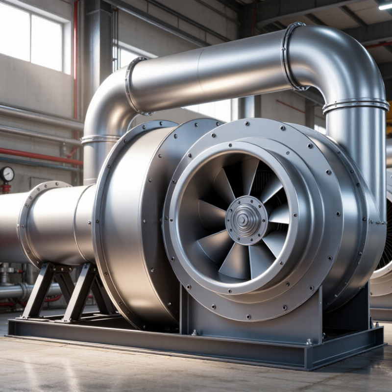
| Airflow | Approximately 500–200,000 m³/h depending on the application | Determine the required airflow from the room volume, process load, air-change rate, or equipment duty. Add only a justified design allowance rather than oversizing the fan. | Small and medium airflow duties commonly use compact direct-drive fans. Higher airflow duties generally require larger impellers or multiple fans. | Select a motor whose rated power covers the fan duty at the required operating point, including service margin. | Airflow should be stated at the actual operating condition. A fan selected only by nominal airflow may fail to meet the required pressure. |
| Total Pressure | Common HVAC and ventilation duties: about 300–2,500 Pa. Industrial process duties may exceed 5,000 Pa. | Calculate duct, filter, coil, damper, silencer, and terminal losses. Use the fan curve to verify airflow and pressure together. | Use a larger or faster fan when pressure is high, but verify noise, efficiency, and impeller tip speed before increasing speed. | Choose a motor based on absorbed shaft power at the selected duty point, not simply on airflow. | Static pressure and total pressure are not interchangeable. Confirm which pressure definition is used on the fan schedule. |
| Air Density and Temperature | Standard reference air: approximately 1.20 kg/m³ at 20°C and sea-level pressure | Correct the fan selection for temperature, altitude, humidity, and gas composition when they differ materially from standard air. | Hot or low-density air may require a larger volume flow or a speed adjustment to deliver the required mass flow and pressure. | Use a motor and insulation system suitable for the ambient temperature and the fan-cooling arrangement. | Fan pressure and power calculations are density-sensitive. High-temperature applications may also require shaft, bearing, and material upgrades. |
| Fan Size | Impeller diameter is selected from the fan performance curve, commonly ranging from approximately 200 to 2,000 mm. | Choose the smallest practical fan that meets the duty near its efficient operating region without excessive speed or noise. | Increasing impeller diameter generally increases airflow and pressure capability at a given speed, subject to the specific fan design. | Confirm that the motor frame, shaft, bearings, and base can accommodate the selected impeller and rotational speed. | Do not select size from duct diameter alone. The fan outlet and duct connection may require transitions. |
| Operating Point | The intersection of the system resistance curve and the fan performance curve | Plot the required airflow and total pressure on the manufacturer’s certified fan curve. Check the complete operating range. | Prefer operation near the fan’s stable, efficient region rather than at the extreme left or right side of the curve. | Allow speed control where the duty varies significantly, provided the motor and drive are compatible with variable-frequency operation. | System resistance typically increases approximately with the square of airflow in turbulent duct systems. |
| Drive Type | Direct drive or belt drive | Select according to required speed range, maintenance access, efficiency target, cleanliness, and space constraints. | Direct drive: compact, low maintenance, no belt losses. Belt drive: flexible speed adjustment and useful for larger or specialized fans. | Direct-drive motors must match the impeller speed. Belt-drive motors may run at a convenient standard speed with pulley selection. | Belt systems require alignment, tension checks, replacement intervals, and guarding. Direct drive avoids these tasks but may offer less mechanical speed flexibility. |
| Motor Power | Typical commercial and industrial fan motors range from approximately 0.25 to 250 kW. | Calculate absorbed power using airflow, pressure, air density, and total fan efficiency. Select the next suitable standard motor rating. | Avoid excessive oversizing because lightly loaded motors may operate inefficiently and can complicate control. | Use a motor rating that covers the maximum absorbed power over the complete fan curve, not only the design point. | For a preliminary estimate: fan power ≈ airflow × pressure ÷ overall efficiency, using consistent SI units. |
| Motor Efficiency | Use the applicable regional efficiency requirement; premium-efficiency motors are commonly preferred for continuously operated fans. | Compare lifecycle energy cost, annual operating hours, part-load behavior, and control method rather than purchase price alone. | High-efficiency motor selection is most valuable for fans operating many hours per year or at relatively high load. | Verify compatibility between the motor, variable-frequency drive, minimum speed, cooling method, and electromagnetic requirements. | Efficiency classes and legal requirements vary by jurisdiction and motor rating. Confirm the current local standard before procurement. |
| Speed Control | Fixed speed, stepped speed, variable-frequency drive, or electronically commutated control | Use variable speed when airflow demand changes, energy reduction is important, or accurate process control is required. | Variable speed can reduce throttling losses, but the fan must remain within its permitted speed range and stable operating zone. | Specify inverter-duty suitability, minimum operating frequency, bearing protection, motor cooling, and drive bypass requirements where applicable. | Fan affinity laws indicate that airflow varies approximately with speed, pressure with speed squared, and power with speed cubed for geometrically similar operation. |
| Electrical Supply | Common supplies include single-phase or three-phase systems at the site’s available voltage and frequency. | Confirm voltage, frequency, available fault current, starting method, control signal, and electrical enclosure requirements. | Three-phase motors are generally preferred for medium and large industrial fans because of smoother operation and practical power capacity. | Specify rated voltage, frequency, phase, full-load current, starting current, protection class, and terminal arrangement. | Electrical selection must comply with the installation country’s wiring, protection, and machinery-safety requirements. |
| Noise | Noise limits depend on the occupied space, boundary location, operating schedule, and local regulations. | Review sound power and sound pressure data across octave bands where acoustic compliance is important. | Larger fans operating at lower speed are often quieter than smaller fans delivering the same duty at very high speed. | Use speed control, vibration isolation, flexible connections, silencers, or acoustic enclosures where required. | Noise may come from the fan, motor, drive, duct breakout, turbulence, or structure-borne vibration; treating only the fan may not solve the problem. |
| Air Cleanliness | Clean air, dusty air, fibrous air, corrosive gas, grease-laden air, or high-temperature process gas | Identify particle size, concentration, moisture, corrosiveness, explosibility, and expected fouling rate before selecting the construction. | Clean-air fans may use standard impellers. Dusty or fibrous streams may require reinforced, non-clogging, abrasion-resistant, or cleanable designs. | Keep the motor outside the contaminated airstream unless the motor enclosure and certification are specifically suitable. | For explosive atmospheres, equipment classification, temperature class, grounding, and certification must be determined by a qualified engineer. |
| Installation Position | Indoor, outdoor, roof-mounted, wall-mounted, suspended, or equipment-integrated installation | Check access, lifting route, foundation strength, drainage, weather exposure, service clearance, and duct connection loads. | Use weather-resistant construction and suitable protective treatment for outdoor installations. Provide adequate inlet and outlet clearance. | Specify motor environmental protection, anti-condensation heating where needed, and local isolation provisions. | Improper inlet elbows, abrupt transitions, or nearby obstructions can reduce performance and increase noise and vibration. |
| Vibration and Bearings | Vibration limits should follow the applicable fan, machinery, and site standards. | Specify balancing grade, bearing arrangement, monitoring points, and allowable vibration level for the application. | High-speed or belt-driven fans need careful balancing, alignment, and structural support. Flexible connectors should not carry duct weight. | Select sealed or regreasable bearings according to speed, temperature, duty cycle, and maintenance strategy. | Persistent vibration can result from imbalance, misalignment, resonance, bearing damage, poor foundations, or aerodynamic instability. |
| Maintenance and Service Life | Review expected operating hours, duty cycle, access frequency, and planned maintenance intervals. | Choose components that can be inspected, lubricated, cleaned, and replaced without major dismantling. | Direct drive generally reduces routine mechanical maintenance. Belt drive requires periodic belt and pulley inspection. | Provide overload protection, thermal protection, accessible isolation, and spare-part availability for the expected service period. | Keep filters, coils, impellers, and inlet screens clean; contamination can increase system resistance and reduce airflow. |
| Final Selection Check | Airflow, pressure, efficiency, noise, speed, power, temperature, materials, controls, and compliance | Request a complete duty schedule and verify the fan at the design point and relevant turndown points. | Select the configuration that meets the duty with reasonable margin while avoiding unnecessary oversizing. | Confirm motor nameplate data, control compatibility, protection, efficiency requirement, and commissioning settings. | Final selection should be validated against certified performance data and the project’s applicable codes and safety requirements. |