


- Home
- A-Z Catalogue
- Products
- Valves
- Cetop
- Manual Directional Valves
- Proportional Valves
- Poppet Valves
- High-Speed Linear Servo Valves
- All High-Speed Linear Servo Valves
- Cetop 10 (NG32) Two Stage Type High Speed Linear Servo Valves – LSVHG-10
- Cetop 10 (NG32) Two Stage Type High Speed Linear Servo Valves – LSVHG-10 (With Fail-Safe)
- Cetop 8 (NG25) Two Stage Type High Speed Linear Servo Valves – LSVHG-06
- Cetop 8 (NG25) Two Stage Type High Speed Linear Servo Valves – LSVHG-06 (With Fail-Safe)
- Cetop 7 (NG16) Two Stage Type High Speed Linear Servo Valves – LSVHG-04
- Cetop 7 (NG16) Two Stage Type High Speed Linear Servo Valves – LSVHG-04 (With Fail-Safe)
- Cetop 5 (NG10) Direct Type High Speed Linear Servo Valves – LSVG-03
- Cetop 5 (NG10) OBE Type Direct Operated Linear Servo Valves – LSVG-03-EH
- Cetop 3 (NG6) OBE Type Direct Operated Linear Servo Valves – LSVG-01-EH
- Pumps
- Pressure control
- Flow Control Valves
- Pressure Control Valves
- All Pressure Control Valves
- Brake Valves
- Direct Relief Valve
- Low Noise Solenoid Controlled Relief Valves
- Low Noise Pilot Operated Relief Valves
- Pilot Operated Relief Valves
- Pressure reducing and relieving valves
- Pressure reducing and check valves
- Pressure control valves
- Remote Control Relief Valves
- Solenoid Controlled Relief Valves – BSG
- Solenoid Controlled Relief Valves – BST
- Unloading relief valves
- Check valves
- Environmental
- Valves
- Hydraulic Systems
- Power pack
- About Us
- Contact
- Blog

How to Choose a Hydraulic Control Valve in 2026?
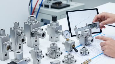
Choosing a hydraulic control valve in 2026 requires more than matching pressure and port size. Modern systems demand accurate flow control, lower energy use, safer operation, and reliable digital communication. A valve that performs well on a test bench may behave differently beside a hot pump, long hose, or contaminated filter.
Peter Nachtwey, a recognized hydraulic motion-control specialist, captures this practical truth: “The valve is only one part of the control system.” His observation matters because valve selection affects the pump, actuator, sensors, controller, piping, and maintenance plan. Engineers should examine operating pressure, peak flow, response time, leakage, fluid type, temperature, and duty cycle. Small details matter. A two-millisecond response may be valuable in a robotic axis, but unnecessary in a slow lifting platform.
Field experience also shows that catalog data can create false confidence. Rated flow is not always delivered flow. Noise figures may depend on ideal installation conditions. Even a premium hydraulic control valve can fail when filtration, wiring, or commissioning is neglected. That is uncomfortable, but useful to remember.
This guide explains how to compare directional, pressure, flow, proportional, and servo valves for real applications in 2026. It considers energy efficiency, diagnostics, cybersecurity expectations, replacement access, and lifecycle cost. Standards and manufacturer specifications remain essential references. Still, every choice deserves verification under actual load. A careful engineer asks one more question: what happens when conditions are no longer perfect?
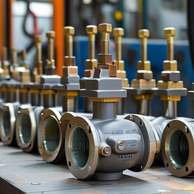
Table of Contents
[Hide]
Hydraulic Control Valve Basics and Operating Principles
Hydraulic control valves regulate fluid direction, pressure, and speed inside a hydraulic circuit.
Their basic action is simple: a spool, poppet, or cartridge changes an internal flow path. Small movements can control large actuators.
A directional valve sends oil toward one side of a cylinder or motor.
A pressure valve limits force by opening when pressure reaches a set value.
A flow-control valve restricts movement speed, much like narrowing a water pipe.
Pilot-operated valves use pressure signals to control larger flows with less manual effort. During commissioning, technicians should compare the valve symbol with the real port arrangement. A drawing can look correct while the installed orientation is wrong. That mistake is surprisingly common.
Tips:
Check flow rate, pressure rating, fluid cleanliness, temperature range, and port size together. Never select a valve by pressure alone. Observe the actuator under load, not only on a workbench. Listen for chatter, inspect leakage, and record actual pressure readings.
Digital sensors can improve monitoring, but they cannot repair poor sizing. In 2026, proportional and electronically monitored valves offer finer control, yet they still depend on stable hydraulic basics. Response time, fail-safe behavior, and electrical compatibility deserve equal attention.
A valve that performs well when cold may respond differently after hours of operation. Testing should include those conditions.
Some selection decisions remain imperfect because machine duty cycles are estimated, not measured. Rechecking those assumptions can prevent expensive redesigns.
Related Posts
-
Understanding the Role of Hydraulic Valves in Modern Industrial Applications
-
7 Essential Tips for Choosing the Right Hydraulic Valve for Your Application
-

Why Flow Control Valve is Essential for Effective System Performance
-
2026 Best Hydraulic Valve Innovations for Enhanced Performance?
-
How to Choose the Right Hydraulic Control Valve for Your Needs
-

Unlocking Efficiency: The Vital Role of Hydraulic Pressure Relief Valves in Industrial Systems





