


- Home
- A-Z Catalogue
- Products
- Valves
- Cetop
- Manual Directional Valves
- Proportional Valves
- Poppet Valves
- High-Speed Linear Servo Valves
- All High-Speed Linear Servo Valves
- Cetop 10 (NG32) Two Stage Type High Speed Linear Servo Valves – LSVHG-10
- Cetop 10 (NG32) Two Stage Type High Speed Linear Servo Valves – LSVHG-10 (With Fail-Safe)
- Cetop 8 (NG25) Two Stage Type High Speed Linear Servo Valves – LSVHG-06
- Cetop 8 (NG25) Two Stage Type High Speed Linear Servo Valves – LSVHG-06 (With Fail-Safe)
- Cetop 7 (NG16) Two Stage Type High Speed Linear Servo Valves – LSVHG-04
- Cetop 7 (NG16) Two Stage Type High Speed Linear Servo Valves – LSVHG-04 (With Fail-Safe)
- Cetop 5 (NG10) Direct Type High Speed Linear Servo Valves – LSVG-03
- Cetop 5 (NG10) OBE Type Direct Operated Linear Servo Valves – LSVG-03-EH
- Cetop 3 (NG6) OBE Type Direct Operated Linear Servo Valves – LSVG-01-EH
- Pumps
- Pressure control
- Flow Control Valves
- Pressure Control Valves
- All Pressure Control Valves
- Brake Valves
- Direct Relief Valve
- Low Noise Solenoid Controlled Relief Valves
- Low Noise Pilot Operated Relief Valves
- Pilot Operated Relief Valves
- Pressure reducing and relieving valves
- Pressure reducing and check valves
- Pressure control valves
- Remote Control Relief Valves
- Solenoid Controlled Relief Valves – BSG
- Solenoid Controlled Relief Valves – BST
- Unloading relief valves
- Check valves
- Environmental
- Valves
- Hydraulic Systems
- Power pack
- About Us
- Contact
- Blog

10 Tips for Choosing the Right PSC Tool Holder?
Choosing the right Psc Tool Holder can determine whether a machining process feels controlled or constantly troublesome. It affects rigidity, runout, tool life, surface finish, and operator confidence. A holder may look precise on a catalog page, yet perform poorly beside a vibrating machine spindle.
Dr. Christian Brecher, a respected production-technology researcher, offers a practical reminder: “The interface determines how reliably the cutting process performs.” That idea matters when comparing PSC holders. The taper standard is only one part of the decision. Buyers must also examine clamping force, pull-stud compatibility, balance quality, coolant delivery, gauge length, and the machine’s actual spindle condition.
Small details often become expensive problems. A holder with excessive projection can amplify vibration during deep pocket milling. A damaged contact face can create uneven seating. Poor balance may leave fine lines across an otherwise acceptable surface. These signs are easy to overlook during purchasing.
This guide presents 10 Tips for Choosing the Right PSC Tool Holder, using workshop experience and measurable selection criteria. It considers real cutting conditions, not only product descriptions. Speed matters. So does maintenance.
There is no perfect holder for every operation. That assumption deserves criticism. A heavy roughing holder may stabilize a steel cut, but it can be excessive for light aluminum work. Conversely, a lightweight option may save money while sacrificing rigidity. The better choice comes from matching the holder to the machine, tool, material, and cutting strategy. Reliable decisions begin with evidence, careful inspection, and a willingness to question familiar habits.
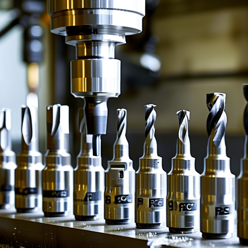
Table of Contents [Hide]
Define PSC Tool Holder Standards and Machine Compatibility
10 Tips for Choosing the Right PSC Tool Holder
Define PSC Tool Holder Standards and Machine Compatibility
Choosing a PSC tool holder starts with standards, not appearance. ISO 26623-1 defines the polygonal shank interface and its critical dimensions. These include the taper, flange contact, and drive geometry. Verify the machine spindle specification before ordering. A holder may look correct but still fail to seat accurately.
Check the spindle size, pull-stud design, gauge length, automatic tool changer clearance, and maximum speed. Measure the actual distance from the spindle face to the workpiece. A longer holder can improve access, yet it may reduce rigidity. Small errors become visible as chatter, poor surface finish, or uneven tool wear. Measure twice. Not always.
Deloitte’s 2024 Global Smart Manufacturing and Operations Survey found that 86% of manufacturers expect smart manufacturing to become a major competitiveness driver within five years. This makes repeatable tool data increasingly important. Record holder dimensions, runout, balance grade, coolant delivery, and tool offset values. ISO 230 supports machine-tool accuracy evaluation, but it does not replace a real compatibility check. I have seen teams trust catalog dimensions too quickly. A simple trial with a certified gauge and a clean spindle nose often reveals the overlooked issue. Check the tool changer arm, adjacent pockets, and coolant ports under actual operating conditions. Safety clearance matters.





