


- Home
- A-Z Catalogue
- Products
- Valves
- Cetop
- Manual Directional Valves
- Proportional Valves
- Poppet Valves
- High-Speed Linear Servo Valves
- All High-Speed Linear Servo Valves
- Cetop 10 (NG32) Two Stage Type High Speed Linear Servo Valves – LSVHG-10
- Cetop 10 (NG32) Two Stage Type High Speed Linear Servo Valves – LSVHG-10 (With Fail-Safe)
- Cetop 8 (NG25) Two Stage Type High Speed Linear Servo Valves – LSVHG-06
- Cetop 8 (NG25) Two Stage Type High Speed Linear Servo Valves – LSVHG-06 (With Fail-Safe)
- Cetop 7 (NG16) Two Stage Type High Speed Linear Servo Valves – LSVHG-04
- Cetop 7 (NG16) Two Stage Type High Speed Linear Servo Valves – LSVHG-04 (With Fail-Safe)
- Cetop 5 (NG10) Direct Type High Speed Linear Servo Valves – LSVG-03
- Cetop 5 (NG10) OBE Type Direct Operated Linear Servo Valves – LSVG-03-EH
- Cetop 3 (NG6) OBE Type Direct Operated Linear Servo Valves – LSVG-01-EH
- Pumps
- Pressure control
- Flow Control Valves
- Pressure Control Valves
- All Pressure Control Valves
- Brake Valves
- Direct Relief Valve
- Low Noise Solenoid Controlled Relief Valves
- Low Noise Pilot Operated Relief Valves
- Pilot Operated Relief Valves
- Pressure reducing and relieving valves
- Pressure reducing and check valves
- Pressure control valves
- Remote Control Relief Valves
- Solenoid Controlled Relief Valves – BSG
- Solenoid Controlled Relief Valves – BST
- Unloading relief valves
- Check valves
- Environmental
- Valves
- Hydraulic Systems
- Power pack
- About Us
- Contact
- Blog

How to Choose Low Voltage Switchgear for Your Project?
Choosing Low Voltage Switchgear for a project is a practical decision, not a catalog exercise. The right assembly must manage expected loads, fault levels, operating conditions, and future expansion. A factory, office tower, or water facility may need completely different protection and enclosure features. Small details matter. Cable entry direction, ambient temperature, maintenance access, and available floor space can affect the final selection.
A reliable evaluation begins with verified project data. Confirm the system voltage, frequency, short-circuit current, load profile, and earthing arrangement. Then compare rated current, breaking capacity, busbar construction, protection settings, and ingress protection. Check whether the equipment follows applicable requirements, such as IEC 61439, while confirming local regulations and utility rules. Manufacturer test reports, routine verification records, and clear technical drawings provide stronger evidence than impressive brochures. Ask how replacement breakers will be sourced years later.
Site experience also deserves attention. A well-designed panel should leave safe working space around terminals and removable covers. Labels must remain readable after installation. Heat calculations should reflect real conditions, including sunlight, dust, and grouped cables. A neat spreadsheet can still mislead. Project assumptions often change after procurement. Therefore, review the design with electricians, consultants, and the equipment manufacturer before approval. Low Voltage Switchgear should support dependable operation, safe maintenance, and sensible lifecycle costs. The cheapest offer may become expensive when access is poor or spare parts disappear. Careful selection is not perfect, but it reduces avoidable surprises.
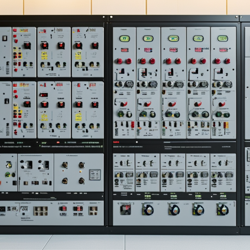
Table of Contents [Hide]
Define System Voltage and Fault Levels: ≤1,000 V AC or 1,500 V DC
Before choosing low voltage switchgear, confirm the system voltage at the equipment terminals. Low voltage generally means up to 1,000 V AC or 1,500 V DC. Do not rely only on the nominal supply label. Check frequency, phase arrangement, earthing method, and voltage tolerance. A 400 V three-phase system requires different clearances and insulation coordination from a 690 V system.
Then establish the available fault level at the installation point. Request data from the utility, transformer manufacturer, or a verified short-circuit study. Record the prospective short-circuit current, peak current, and fault duration. For an assembly, compare these values with its short-time withstand current, peak withstand current, and short-circuit rating. The protective device must interrupt the fault safely. Its coordination with downstream breakers also matters.
Small details change the result.
Cable length, transformer impedance, and parallel feeders can raise or reduce fault current. I have seen preliminary drawings omit future generators, creating an unrealistically low fault level. That error can affect enclosure strength and protection settings. Recheck the study after major design changes. Use equipment tested under applicable assembly standards, and keep test reports, calculations, and settings accessible for inspection. A technically acceptable selection can still fail if field wiring differs from the design. Perform a site verification before energizing, even when the paperwork appears complete.





