


- Home
- A-Z Catalogue
- Products
- Valves
- Cetop
- Manual Directional Valves
- Proportional Valves
- Poppet Valves
- High-Speed Linear Servo Valves
- All High-Speed Linear Servo Valves
- Cetop 10 (NG32) Two Stage Type High Speed Linear Servo Valves – LSVHG-10
- Cetop 10 (NG32) Two Stage Type High Speed Linear Servo Valves – LSVHG-10 (With Fail-Safe)
- Cetop 8 (NG25) Two Stage Type High Speed Linear Servo Valves – LSVHG-06
- Cetop 8 (NG25) Two Stage Type High Speed Linear Servo Valves – LSVHG-06 (With Fail-Safe)
- Cetop 7 (NG16) Two Stage Type High Speed Linear Servo Valves – LSVHG-04
- Cetop 7 (NG16) Two Stage Type High Speed Linear Servo Valves – LSVHG-04 (With Fail-Safe)
- Cetop 5 (NG10) Direct Type High Speed Linear Servo Valves – LSVG-03
- Cetop 5 (NG10) OBE Type Direct Operated Linear Servo Valves – LSVG-03-EH
- Cetop 3 (NG6) OBE Type Direct Operated Linear Servo Valves – LSVG-01-EH
- Pumps
- Pressure control
- Flow Control Valves
- Pressure Control Valves
- All Pressure Control Valves
- Brake Valves
- Direct Relief Valve
- Low Noise Solenoid Controlled Relief Valves
- Low Noise Pilot Operated Relief Valves
- Pilot Operated Relief Valves
- Pressure reducing and relieving valves
- Pressure reducing and check valves
- Pressure control valves
- Remote Control Relief Valves
- Solenoid Controlled Relief Valves – BSG
- Solenoid Controlled Relief Valves – BST
- Unloading relief valves
- Check valves
- Environmental
- Valves
- Hydraulic Systems
- Power pack
- About Us
- Contact
- Blog

7 Tips to Choose the Best Deep Drill Machine?
Choosing a Deep Drill Machine is not simply a matter of comparing motor power and purchase price. In a real workshop, the machine must produce accurate holes repeatedly, often through tough steel, cast iron, or engineered components. Operators notice details that catalogues may hide: vibration at the spindle, coolant reaching the cutting edge, and chips leaving the bore without clogging. Small details matter. A technically impressive model can still disappoint when its table flexes or its controls feel unclear. This guide introduces seven practical tips for evaluating drilling capacity, spindle performance, workholding, cooling, automation, safety, and long-term service support. Each point connects specifications with daily use, because a machine is judged beside the workpiece, not only on a datasheet.
Reliable selection begins with the application. Hole diameter, depth-to-diameter ratio, material hardness, tolerance, production volume, and available floor space should shape the decision. That assumption fails. More power does not automatically deliver better accuracy. A balanced spindle, rigid structure, suitable tooling, and stable coolant flow may matter more for consistent results. Experienced technicians also examine maintenance access, replacement-part availability, operator training, and manufacturer documentation. These factors influence downtime and total ownership cost long after installation. No checklist is perfect. Conditions change, and an honest evaluation may reveal that a cheaper machine suits occasional work, while a robust system earns its cost in continuous production. The following tips support careful comparison, practical testing, and informed discussions with qualified suppliers.
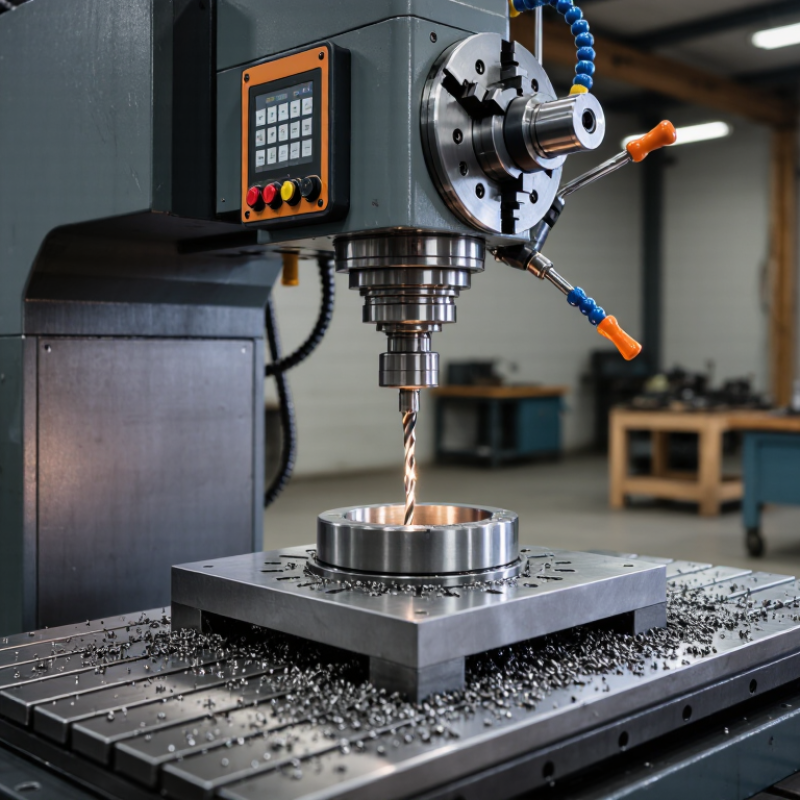
Table of Contents [Hide]
Define Deep Drilling by the 10:1 Hole-Depth-to-Diameter Industry Ratio
7 Tips to Choose the Best Deep Drill Machine
Deep drilling usually means a hole with a depth-to-diameter ratio of at least 10:1. For example, a 200 mm deep hole may require a 20 mm diameter. This ratio matters because long holes increase deflection, heat, chip blockage, and alignment errors. In practical machining, the opening can look accurate while the bottom drifts slightly.
Tip 1: Match the machine to the ratio, material, and required tolerance. A rigid frame, stable spindle, and controlled feed reduce vibration. Tip 2: Check the cooling and chip-removal system. Deep holes need steady coolant flow and a clear path for chips. Dry cutting may create heat quickly. Tip 3: Review real cutting data, not only catalog claims. Ask for hole-depth tests using similar steel, aluminum, or difficult alloys. Experience shows that a machine performing well at 8:1 may struggle at 15:1.
Tip 4: Examine tool guidance and spindle runout. Small alignment errors become larger down a deep hole. Tip 5: Confirm that the machine supports pecking, gun drilling, or other suitable methods. Tip 6: Measure the finished hole with reliable gauges, including straightness and diameter checks. Tip 7: Consider operator training and maintenance access. A technically strong machine can still produce poor results when setup habits are inconsistent. I would also challenge one assumption: the 10:1 ratio is a useful industry boundary, not a guarantee of quality. Material hardness, tool geometry, coolant pressure, and tolerance may demand a more capable system.





