


- Home
- A-Z Catalogue
- Products
- Valves
- Cetop
- Manual Directional Valves
- Proportional Valves
- Poppet Valves
- High-Speed Linear Servo Valves
- All High-Speed Linear Servo Valves
- Cetop 10 (NG32) Two Stage Type High Speed Linear Servo Valves – LSVHG-10
- Cetop 10 (NG32) Two Stage Type High Speed Linear Servo Valves – LSVHG-10 (With Fail-Safe)
- Cetop 8 (NG25) Two Stage Type High Speed Linear Servo Valves – LSVHG-06
- Cetop 8 (NG25) Two Stage Type High Speed Linear Servo Valves – LSVHG-06 (With Fail-Safe)
- Cetop 7 (NG16) Two Stage Type High Speed Linear Servo Valves – LSVHG-04
- Cetop 7 (NG16) Two Stage Type High Speed Linear Servo Valves – LSVHG-04 (With Fail-Safe)
- Cetop 5 (NG10) Direct Type High Speed Linear Servo Valves – LSVG-03
- Cetop 5 (NG10) OBE Type Direct Operated Linear Servo Valves – LSVG-03-EH
- Cetop 3 (NG6) OBE Type Direct Operated Linear Servo Valves – LSVG-01-EH
- Pumps
- Pressure control
- Flow Control Valves
- Pressure Control Valves
- All Pressure Control Valves
- Brake Valves
- Direct Relief Valve
- Low Noise Solenoid Controlled Relief Valves
- Low Noise Pilot Operated Relief Valves
- Pilot Operated Relief Valves
- Pressure reducing and relieving valves
- Pressure reducing and check valves
- Pressure control valves
- Remote Control Relief Valves
- Solenoid Controlled Relief Valves – BSG
- Solenoid Controlled Relief Valves – BST
- Unloading relief valves
- Check valves
- Environmental
- Valves
- Hydraulic Systems
- Power pack
- About Us
- Contact
- Blog

What Is a Value Vacuum Pump and How Does It Work?
A Value Vacuum Pump is a practical tool for removing air, moisture, and non-condensable gases from sealed systems. It is widely used in refrigeration, air-conditioning, automotive service, and laboratory work. Its purpose sounds simple, but reliable evacuation requires more than connecting a hose and switching it on. Pump size, oil condition, hose diameter, leakage, and system temperature can all change the final result.
Vacuum-technology author John F. O’Hanlon explains the basic challenge clearly: “A vacuum is not empty space; it is a gas-handling problem.” A Value Vacuum Pump usually uses an oil-sealed rotary-vane mechanism. As the rotor turns, the vanes capture gas from the inlet, compress it, and release it through the exhaust port. Fresh pump oil helps seal internal clearances and carries away heat. The process repeats until pressure falls to the pump’s working limit.
In practice, the lowest advertised micron rating does not guarantee a fast evacuation. A narrow charging hose may restrict performance. Damp oil may also hide a deeper problem. A micron gauge near the system gives more trustworthy evidence than the pump’s sound or vibration. That detail matters.
This guide will examine how a Value Vacuum Pump works, what its main components do, and how technicians can use it responsibly. Some explanations may appear basic. They are still worth checking, because small mistakes often create large service delays. A careful technician watches the readings, inspects connections, and questions results that seem unusually perfect.
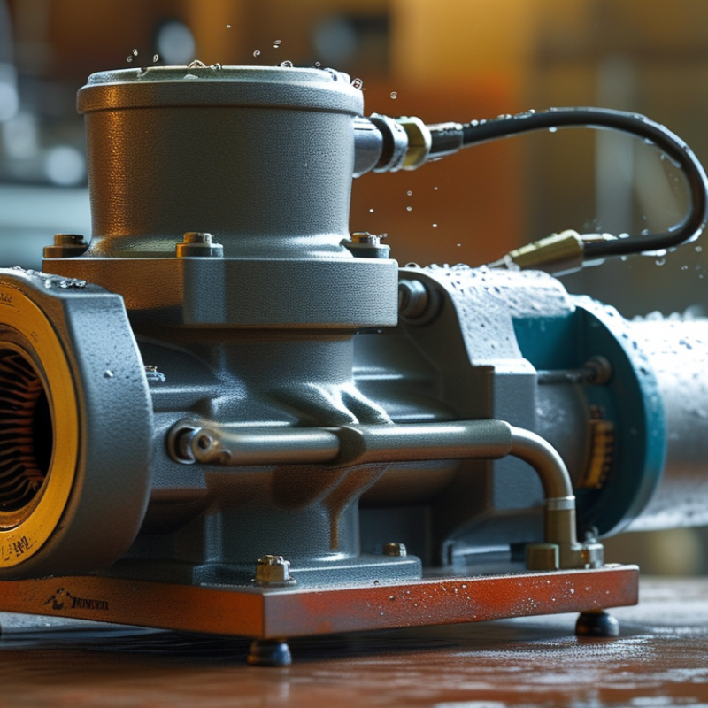
Table of Contents [Hide]
Definition and Purpose of a Value Vacuum Pump
What Is a Value Vacuum Pump and How Does It Work?
Definition and Purpose of a Value Vacuum Pump
The term “value vacuum pump” can be confusing. In practice, it often describes a vacuum pump used with valve-controlled equipment. Its purpose is to remove air, moisture, or other gases from a sealed system. This creates lower pressure inside the chamber or line.
The pump uses a motor to drive an internal mechanism, such as rotary vanes or a diaphragm. As the mechanism moves, it captures gas and pushes it toward the exhaust port. A valve controls the flow and helps prevent unwanted air from returning. Technicians may use this setup during refrigeration service, laboratory preparation, packaging, or industrial maintenance. The correct pump depends on vacuum depth, gas type, flow rate, and system size. One detail is easy to miss: a strong pump cannot compensate for a leaking connection.
Tips
Check every hose, gasket, and valve before starting. Small leaks matter. Use a vacuum gauge near the equipment, not only near the pump. This gives a more realistic reading. Change contaminated oil when the model requires it. Moisture can reduce performance and damage internal parts. I have found that rushing the final leak check causes avoidable errors. Let the pump run steadily, and watch whether the pressure continues to fall. If it stops too early, inspect the system before blaming the pump. Safety glasses and proper ventilation remain sensible precautions.





