


- Home
- A-Z Catalogue
- Products
- Valves
- Cetop
- Manual Directional Valves
- Proportional Valves
- Poppet Valves
- High-Speed Linear Servo Valves
- All High-Speed Linear Servo Valves
- Cetop 10 (NG32) Two Stage Type High Speed Linear Servo Valves – LSVHG-10
- Cetop 10 (NG32) Two Stage Type High Speed Linear Servo Valves – LSVHG-10 (With Fail-Safe)
- Cetop 8 (NG25) Two Stage Type High Speed Linear Servo Valves – LSVHG-06
- Cetop 8 (NG25) Two Stage Type High Speed Linear Servo Valves – LSVHG-06 (With Fail-Safe)
- Cetop 7 (NG16) Two Stage Type High Speed Linear Servo Valves – LSVHG-04
- Cetop 7 (NG16) Two Stage Type High Speed Linear Servo Valves – LSVHG-04 (With Fail-Safe)
- Cetop 5 (NG10) Direct Type High Speed Linear Servo Valves – LSVG-03
- Cetop 5 (NG10) OBE Type Direct Operated Linear Servo Valves – LSVG-03-EH
- Cetop 3 (NG6) OBE Type Direct Operated Linear Servo Valves – LSVG-01-EH
- Pumps
- Pressure control
- Flow Control Valves
- Pressure Control Valves
- All Pressure Control Valves
- Brake Valves
- Direct Relief Valve
- Low Noise Solenoid Controlled Relief Valves
- Low Noise Pilot Operated Relief Valves
- Pilot Operated Relief Valves
- Pressure reducing and relieving valves
- Pressure reducing and check valves
- Pressure control valves
- Remote Control Relief Valves
- Solenoid Controlled Relief Valves – BSG
- Solenoid Controlled Relief Valves – BST
- Unloading relief valves
- Check valves
- Environmental
- Valves
- Hydraulic Systems
- Power pack
- About Us
- Contact
- Blog

What Is a VFD PCB Board and How Does It Work?
A Vfd Pcb Board is the electronic control center inside a variable frequency drive. It helps regulate motor speed, torque, and direction with carefully timed electrical signals. In practical applications, this board connects low-voltage control logic with powerful switching components. That connection must remain stable under heat, vibration, dust, and electrical noise.
A typical VFD changes incoming AC power into DC through a rectifier section. Capacitors then smooth the DC bus voltage. An inverter stage uses IGBTs or MOSFETs to create a controlled AC output. The Vfd Pcb Board sends gate-drive signals to these switches, often using pulse-width modulation. By changing output frequency and voltage, the drive adjusts motor performance for pumps, conveyors, fans, and compressors.
It also monitors current, voltage, temperature, and fault conditions. Feedback signals allow the controller to correct operation or shut down safely. This process sounds straightforward. It is not always simple.
Engineers usually inspect circuit diagrams, firmware settings, grounding methods, and thermal paths together. A damaged sensing circuit may appear harmless, yet it can cause unstable motor behavior or repeated trips. The board’s layout also matters. Short signal paths, suitable isolation, and proper shielding can reduce interference.
Reliable manufacturers validate VFD designs through thermal testing, electrical stress checks, and documented protection procedures. Qualified technicians should follow the drive manual and applicable safety requirements before testing any energized equipment. One detail deserves reflection: not every VFD PCB carries the same functions. Some boards manage control logic, while others combine power conversion and protection. Understanding that difference makes diagnosis more accurate and replacement decisions less risky.
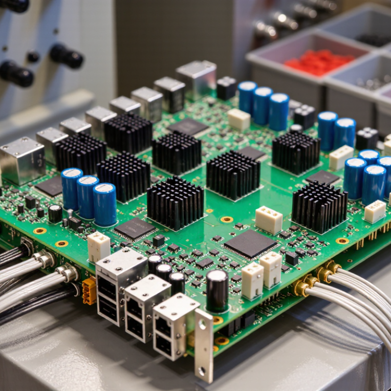
Table of Contents [Hide]
VFD PCB Definition: AC–DC–AC Conversion at 95–98% Efficiency
A VFD PCB board is the circuit platform that helps a variable-frequency drive convert incoming AC power into controlled AC output.
A rectifier first changes the input AC into DC. Capacitors smooth the DC bus, reducing voltage ripple. An inverter stage then switches that DC into AC at a selected frequency and voltage.
This lets a motor run at different speeds. That is the core.
The 95–98% efficiency figure usually describes a well-designed drive under suitable operating conditions, not the bare PCB alone.
Actual efficiency varies with load, switching frequency, cooling, and component condition. For example, a dusty enclosure or loose connection can raise temperatures and increase losses.
Heat still matters. Engineers check board layout, current paths, insulation spacing, and thermal behavior during design and testing.
A practical detail is the DC bus: its voltage can remain hazardous after power is removed, so service procedures must account for stored energy.
Efficiency figures are useful, but they need context.
A drive running lightly loaded may not match a peak rating, and field measurements can reveal losses that a datasheet does not show.





