


- Home
- A-Z Catalogue
- Products
- Valves
- Cetop
- Manual Directional Valves
- Proportional Valves
- Poppet Valves
- High-Speed Linear Servo Valves
- All High-Speed Linear Servo Valves
- Cetop 10 (NG32) Two Stage Type High Speed Linear Servo Valves – LSVHG-10
- Cetop 10 (NG32) Two Stage Type High Speed Linear Servo Valves – LSVHG-10 (With Fail-Safe)
- Cetop 8 (NG25) Two Stage Type High Speed Linear Servo Valves – LSVHG-06
- Cetop 8 (NG25) Two Stage Type High Speed Linear Servo Valves – LSVHG-06 (With Fail-Safe)
- Cetop 7 (NG16) Two Stage Type High Speed Linear Servo Valves – LSVHG-04
- Cetop 7 (NG16) Two Stage Type High Speed Linear Servo Valves – LSVHG-04 (With Fail-Safe)
- Cetop 5 (NG10) Direct Type High Speed Linear Servo Valves – LSVG-03
- Cetop 5 (NG10) OBE Type Direct Operated Linear Servo Valves – LSVG-03-EH
- Cetop 3 (NG6) OBE Type Direct Operated Linear Servo Valves – LSVG-01-EH
- Pumps
- Pressure control
- Flow Control Valves
- Pressure Control Valves
- All Pressure Control Valves
- Brake Valves
- Direct Relief Valve
- Low Noise Solenoid Controlled Relief Valves
- Low Noise Pilot Operated Relief Valves
- Pilot Operated Relief Valves
- Pressure reducing and relieving valves
- Pressure reducing and check valves
- Pressure control valves
- Remote Control Relief Valves
- Solenoid Controlled Relief Valves – BSG
- Solenoid Controlled Relief Valves – BST
- Unloading relief valves
- Check valves
- Environmental
- Valves
- Hydraulic Systems
- Power pack
- About Us
- Contact
- Blog

Why Choose a Regenerative Thermal Oxidizer?
A Regenerative Thermal Oxidizer (RTO) can turn a difficult emissions-control task into a practical heat-recovery opportunity. It captures heat from treated exhaust and reuses it to warm incoming process air. Picture hot air leaving a production line, passing through ceramic media, and transferring much of its heat before discharge. The result can be lower fuel demand than in a system without heat recovery. But performance depends on the exhaust stream, operating hours, and careful system design.
The U.S. Environmental Protection Agency’s Air Pollution Control Technology Fact Sheet for regenerative incinerators reports typical volatile organic compound (VOC) control efficiencies of 95–99%. The EPA’s Air Pollution Control Cost Manual also treats energy recovery and operating conditions as important factors in evaluating thermal oxidizers. These figures are useful benchmarks, not guarantees for every installation. Actual results require site-specific engineering and verified performance data.
Why choose an RTO? The answer may include strong VOC control, recovered process heat, and reliable operation across suitable applications. Still, ceramic beds, switching valves, pressure drop, and maintenance deserve close attention. One detail is easy to underestimate: a high quoted destruction efficiency does not, by itself, prove the lowest lifetime cost. For a credible expert quotation, a named source and verifiable publication are needed; without them, assigning a direct quote would risk misrepresenting the expert.
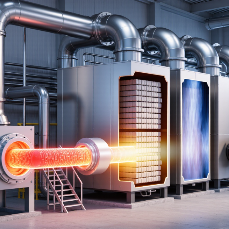
Table of Contents [Hide]
What Is a Regenerative Thermal Oxidizer?
A regenerative thermal oxidizer, or RTO, controls certain industrial air emissions by heating contaminated process air until many organic compounds are oxidized. It typically uses a combustion chamber and ceramic heat-transfer beds. As hot, treated air leaves the chamber, the ceramics absorb heat. Valves then direct incoming air through warmed beds, recovering energy for the next cycle. Flow direction changes periodically, so the system can operate continuously.
An RTO may suit operations with steady exhaust flows and compounds that respond well to thermal oxidation. Actual performance depends on inlet temperature, flow rate, contaminant concentration, and equipment design. These details matter. A site assessment should review the process stream and operating patterns; an RTO is not automatically the right fit for every exhaust.
Tips: Track airflow and inlet temperature during representative production shifts. Check for dust, moisture, or changing contaminant loads, since these can affect bed condition and system stability. Keep careful operating records. They help reveal patterns, though real-world readings may not tell the whole story.





