


- Home
- A-Z Catalogue
- Products
- Valves
- Cetop
- Manual Directional Valves
- Proportional Valves
- Poppet Valves
- High-Speed Linear Servo Valves
- All High-Speed Linear Servo Valves
- Cetop 10 (NG32) Two Stage Type High Speed Linear Servo Valves – LSVHG-10
- Cetop 10 (NG32) Two Stage Type High Speed Linear Servo Valves – LSVHG-10 (With Fail-Safe)
- Cetop 8 (NG25) Two Stage Type High Speed Linear Servo Valves – LSVHG-06
- Cetop 8 (NG25) Two Stage Type High Speed Linear Servo Valves – LSVHG-06 (With Fail-Safe)
- Cetop 7 (NG16) Two Stage Type High Speed Linear Servo Valves – LSVHG-04
- Cetop 7 (NG16) Two Stage Type High Speed Linear Servo Valves – LSVHG-04 (With Fail-Safe)
- Cetop 5 (NG10) Direct Type High Speed Linear Servo Valves – LSVG-03
- Cetop 5 (NG10) OBE Type Direct Operated Linear Servo Valves – LSVG-03-EH
- Cetop 3 (NG6) OBE Type Direct Operated Linear Servo Valves – LSVG-01-EH
- Pumps
- Pressure control
- Flow Control Valves
- Pressure Control Valves
- All Pressure Control Valves
- Brake Valves
- Direct Relief Valve
- Low Noise Solenoid Controlled Relief Valves
- Low Noise Pilot Operated Relief Valves
- Pilot Operated Relief Valves
- Pressure reducing and relieving valves
- Pressure reducing and check valves
- Pressure control valves
- Remote Control Relief Valves
- Solenoid Controlled Relief Valves – BSG
- Solenoid Controlled Relief Valves – BST
- Unloading relief valves
- Check valves
- Environmental
- Valves
- Hydraulic Systems
- Power pack
- About Us
- Contact
- Blog

Why Choose a Vehicle Wedge Barrier for Global Security?
A Vehicle Wedge Barrier offers a practical layer of protection for facilities facing unauthorized vehicle entry risks. Its rising steel wedge creates a visible and physical boundary across access lanes. When correctly specified, it can help protect entrances, loading areas, public venues, and sensitive sites without dominating the surrounding architecture.
The strongest choice begins with a site assessment. Traffic volume, vehicle types, lane width, drainage, climate, and emergency access all matter. A security engineer should review the barrier’s impact rating, operating cycle, foundation design, and control system. Independent test reports and clear manufacturer documentation provide useful evidence. They also deserve careful checking.
Installation quality matters greatly.
In daily operation, staff need simple controls, clear warning signals, and reliable manual procedures. Regular inspections should examine hinges, hydraulic components, sensors, lighting, and surface corrosion. A neglected barrier may look strong while performing poorly. That assumption can fail.
Global projects also require attention to local building codes, accessibility expectations, fire safety planning, and procurement standards. Requirements differ between regions, so one specification cannot suit every site. Experienced suppliers can support design reviews, commissioning, training, and maintenance planning. Still, their recommendations should be compared with independent professional advice.
A Vehicle Wedge Barrier is not a complete security strategy. It should work with trained personnel, suitable perimeter design, traffic management, and documented response procedures. The best solution balances protection, usability, appearance, and long-term cost. It may not be the cheapest option. Yet, when risks are carefully evaluated, it can provide a durable and measurable improvement to vehicle access control.
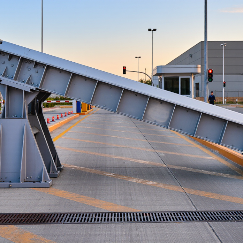
Table of Contents [Hide]
What Is a Vehicle Wedge Barrier?
Why Choose a Vehicle Wedge Barrier for Global Security?
What Is a Vehicle Wedge Barrier?
A vehicle wedge barrier is a rising steel road blocker. It sits flush with the pavement when open. When activated, its angled plate rises and stops or redirects unauthorized vehicles. The design protects entrances, loading areas, checkpoints, and pedestrian zones. Unlike a simple gate, it controls vehicle mass and momentum at the access point. Performance should be checked through recognized standards, such as ASTM F2656 or IWA 14-1. These standards assess vehicle impact resistance, penetration distance, and test conditions. The 2024 Global Terrorism Index recorded 8,352 terrorist attacks worldwide in 2023. However, that report does not isolate vehicle attacks. This limitation matters. Security decisions should not rely on one statistic.
A properly selected wedge barrier combines tested strength, visible warning systems, drainage, lighting, and controlled access. WHO’s Global Status Report on Road Safety 2023 estimates 1.19 million annual road deaths worldwide. That figure concerns road safety, not hostile vehicles, but it reinforces the need for disciplined traffic control. A barrier can reduce risk, yet it cannot replace trained operators or emergency planning. Sometimes, the weakest point is human judgment.
Tips: Match the barrier rating to the site’s largest realistic vehicle. Check stopping distance, foundation depth, power backup, maintenance access, and pedestrian escape routes. Request independent test evidence, not only marketing claims. A site survey may reveal blind corners, poor drainage, or a safer layered design.





