


- Home
- A-Z Catalogue
- Products
- Valves
- Cetop
- Manual Directional Valves
- Proportional Valves
- Poppet Valves
- High-Speed Linear Servo Valves
- All High-Speed Linear Servo Valves
- Cetop 10 (NG32) Two Stage Type High Speed Linear Servo Valves – LSVHG-10
- Cetop 10 (NG32) Two Stage Type High Speed Linear Servo Valves – LSVHG-10 (With Fail-Safe)
- Cetop 8 (NG25) Two Stage Type High Speed Linear Servo Valves – LSVHG-06
- Cetop 8 (NG25) Two Stage Type High Speed Linear Servo Valves – LSVHG-06 (With Fail-Safe)
- Cetop 7 (NG16) Two Stage Type High Speed Linear Servo Valves – LSVHG-04
- Cetop 7 (NG16) Two Stage Type High Speed Linear Servo Valves – LSVHG-04 (With Fail-Safe)
- Cetop 5 (NG10) Direct Type High Speed Linear Servo Valves – LSVG-03
- Cetop 5 (NG10) OBE Type Direct Operated Linear Servo Valves – LSVG-03-EH
- Cetop 3 (NG6) OBE Type Direct Operated Linear Servo Valves – LSVG-01-EH
- Pumps
- Pressure control
- Flow Control Valves
- Pressure Control Valves
- All Pressure Control Valves
- Brake Valves
- Direct Relief Valve
- Low Noise Solenoid Controlled Relief Valves
- Low Noise Pilot Operated Relief Valves
- Pilot Operated Relief Valves
- Pressure reducing and relieving valves
- Pressure reducing and check valves
- Pressure control valves
- Remote Control Relief Valves
- Solenoid Controlled Relief Valves – BSG
- Solenoid Controlled Relief Valves – BST
- Unloading relief valves
- Check valves
- Environmental
- Valves
- Hydraulic Systems
- Power pack
- About Us
- Contact
- Blog

How to Choose a Hydraulic Pressure Control Valve?
Choosing a hydraulic pressure control valve is a practical engineering decision, not a simple catalog search. The correct valve must match pressure, flow, fluid type, temperature, connection size, and control requirements. A small mismatch can cause unstable pressure, excessive heat, noise, or premature component failure.
Hydraulic educator Harry L. Stewart wrote, “Pressure is caused by resistance to flow.” This principle explains why valve selection must begin with the machine’s real operating conditions. A relief valve may protect the circuit from dangerous overpressure. A reducing valve may protect a sensitive actuator. A sequence valve may control when another function begins. Each hydraulic pressure control valve has a different role.
Look beyond the maximum rating. Check the normal working pressure, peak pressure, minimum controllable pressure, and expected flow range. Review the manufacturer’s pressure-flow curves, leakage data, response time, and adjustment method. Field experience also matters. A valve installed near a vibrating pump may need stronger mounting and better filtration. Contaminated oil can make a precise valve behave unpredictably.
Measure carefully.
This guide explains how to compare valve types, calculate practical requirements, and read technical specifications. It also considers installation position, maintenance access, noise, energy loss, and system safety. No selection is perfect in every situation. An impressive laboratory rating may not reflect cold starts, dirty fluid, or frequent pressure spikes. Engineers should verify assumptions through testing, recorded operating data, and feedback from experienced technicians. The final choice should be technically defensible, serviceable, and suitable for the machine’s actual working environment.
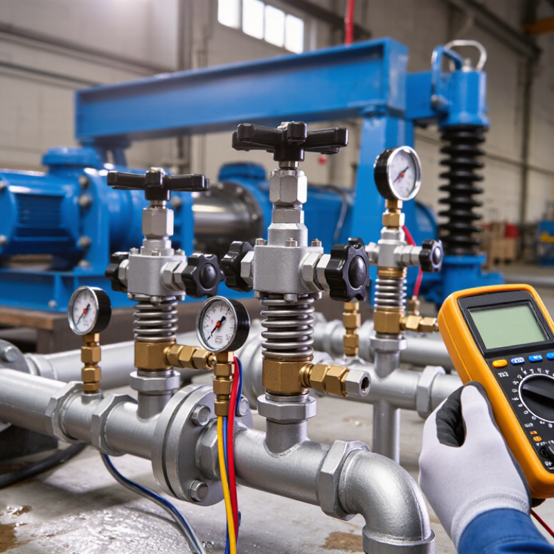
Table of Contents
[Hide]
Define the Circuit’s Pressure Range: 10–35 MPa for Common Systems
How to Choose a Hydraulic Pressure Control Valve?
Define the Circuit’s Pressure Range: 10–35 MPa for Common Systems
Start by mapping the circuit’s real pressure range, not only its design value. Many industrial hydraulic systems operate between 10 and 35 MPa. However, pressure can rise sharply when an actuator stops suddenly. Record normal pressure, peak pressure, and pressure during cold starts. A pressure gauge with suitable accuracy helps reveal these differences.
Choose a valve rated above the highest measured pressure. Leave practical safety margin. For example, a circuit reaching 28 MPa should not use a valve rated only for 30 MPa. Check the valve’s continuous pressure, maximum pressure, flow capacity, and adjustment range. A pressure control valve must also match the fluid type, temperature, port size, and expected contamination level. Small particles can make adjustment unstable.
Field checks matter. I have seen systems that looked suitable on paper but produced noisy, drifting pressure after installation. The cause was often poor filtration or an undersized return line. Check relief settings with a calibrated test gauge, then observe the valve under changing loads. Do not set the valve at its limit. That shortcut saves time initially, but it can shorten service life and hide a design problem. Recheck the setting after warm-up, because fluid temperature changes system behavior.
How to Choose a Hydraulic Pressure Control Valve? - Define the Circuit’s Pressure Range: 10–35 MPa for Common Systems
| Circuit Pressure Range | Typical Valve Function | Recommended Valve Pressure Class | Typical Setting Range | Typical Flow Capacity | Common Fluid Temperature | Selection Guidance |
|---|---|---|---|---|---|---|
| 10–15 MPa | Pressure relief valve | 16 MPa minimum | 10–15 MPa | 10–160 L/min | −20 to 80 °C | Choose a pressure rating above the maximum system pressure and set the valve below the weakest component’s allowable pressure. |
| 10–15 MPa | Pressure-reducing valve | 16 MPa minimum inlet rating | 4–12 MPa downstream | 5–100 L/min | −20 to 80 °C | Use when one branch requires a lower, stable pressure than the main circuit. Confirm the minimum pressure differential required for regulation. |
| 15–21 MPa | Sequence valve | 25 MPa minimum | 8–20 MPa | 10–120 L/min | −20 to 80 °C | Set the sequence pressure high enough to complete the first actuator operation, but below the relief-valve setting. |
| 15–21 MPa | Counterbalance valve | 25 MPa minimum | Load-induced pressure + 20–30% | 5–80 L/min | −20 to 80 °C | Suitable for preventing uncontrolled actuator movement. Select based on load pressure, pilot ratio, flow, and required lowering smoothness. |
| 20–28 MPa | Pressure relief valve | 31.5 MPa minimum | 20–28 MPa | 20–250 L/min | −20 to 80 °C | Verify that the valve’s rated flow is at least equal to the maximum pump flow that may be diverted during pressure relief. |
| 20–28 MPa | Unloading valve | 31.5 MPa minimum | Pressure-dependent | 20–250 L/min | −20 to 80 °C | Use in accumulator or high–low pump circuits to unload the pump when the required pressure or flow condition is reached. |
| 28–35 MPa | Pressure relief valve | 40 MPa minimum | 28–35 MPa | 20–320 L/min | −20 to 80 °C | For high-pressure circuits, check pressure spikes, fatigue rating, mounting interface, and the pressure rating of hoses, fittings, cylinders, and pumps. |
| 28–35 MPa | Pressure-reducing valve | 40 MPa minimum inlet rating | 10–30 MPa downstream | 5–160 L/min | −20 to 80 °C | Confirm the inlet-to-outlet pressure ratio, flow demand, pressure stability, and heat generation before selecting the valve size. |
| Up to 35 MPa | Pressure-compensated flow-control valve | 40 MPa minimum | Controlled by load-sensing differential | 2–120 L/min | −20 to 80 °C | Choose this type when actuator speed must remain relatively stable as load pressure changes. Check the required compensator differential pressure. |
| Up to 35 MPa | Modular or cartridge pressure-control valve | Equal to or above system peak pressure | Application-specific | Application-specific | −20 to 80 °C | Verify cavity dimensions, port size, installation orientation, adjustment method, leakage limits, and compatibility with the manifold material. |
Practical sizing rule: Define the normal operating pressure, maximum pressure spike, required flow rate, fluid viscosity, temperature, and allowable pressure drop. The valve’s maximum working pressure should exceed the circuit’s highest foreseeable pressure, while its setting must remain below the pressure rating of the least-rated component.
Related Posts
-
7 Essential Tips for Choosing the Right Hydraulic Valve for Your Application
-
How to Choose a Hydraulic Control Valve in 2026?
-
Understanding the Role of Hydraulic Valves in Modern Industrial Applications
-
2026 Best Hydraulic Valve Innovations for Enhanced Performance?
-
How to Choose the Right Directional Control Valve for Your Project
-
Understanding the Importance of Hydraulic Pressure Control Valves in Modern Industrial Applications





